W-BOX video teaching free download link, can be watched online:
http://down.avldiy.cn/down_server/W-BOX/video_teaching/
W-BOX video teaching baidu webdisk download link (Password: wtoj):
https://pan.baidu.com/s/1LSr7kx-Ll58dt4S9MUmqjg
W-BOX supporting software download link:
http://box.avldiy.cn/update/w-box/
W-BOX new Firmware download link:
http://down.avldiy.cn/down_server/W-BOX/ipk/
W-BOX technical function:
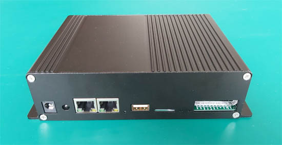
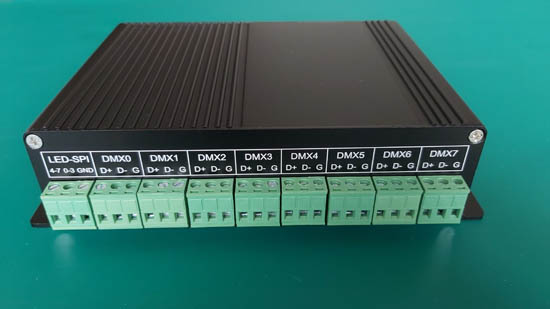
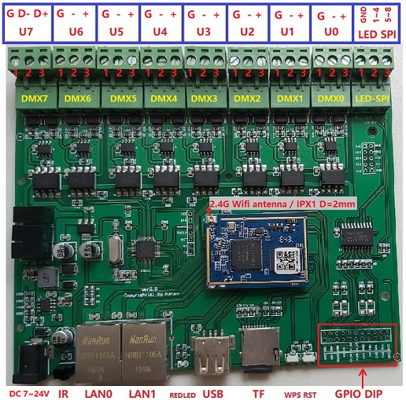
1: The box has 8 isolated DMX512 outputs and 8 WS281x LED lights with SPI output, which can not only control DMX512 devices, but also directly control LED lights;
2: Box has a 150M, 2.4G Wifi;
3: The box has 2 network ports, and the box has its own switch and router. You can cascade more boxes hand in hand through the network cable to form a large lighting control system, without additional switches or routers;
4: The box has an SD card, which can support FAT, FAT32, NTFS, EXT4 formats, and the SD card can save audio and video files and DMX light files for offline playback;
5: The box has a universal USB HOST interface, which can be connected to USB devices such as U disk, USB-Hub, USB sound card, USB mouse, keyboard, USB-RS232 serial port, etc ;
6: The box can play most audio and video files, supports AVI, MPG, WMV, JPG, BMP, GIF, WAV, MP3, FLAC, APE and our dedicated DMX and l3a files, and can map video and DMX files to the lighting;
7: The box has many external interfaces, such as GPIO, I2C, UART, PWM, IR… It can be triggered by external devices to play the offline files of the box, and it can also be connected to external sensors to trigger the control box or control external devices;
8: The box has 1 infrared IR receiver, through learning, it supports more than 99% of the remote controls on the market, and it also has 1 IR infrared transmitter GPIO interface;
9: The box has a webui graphical interface, so the box can be controlled and set through a browser of any platform. There is also a simple console in the webui, which can test and control the lighting through a mobile phone or tablet;
10: There are 2 CPUs in the box, the running system is Linux, and the startup time is about 17 to 23 seconds;
11: The box can receive and process the latest version of Artnet, sACN, ESP, hahan… and other lighting network protocol data at the same time to control the lighting. Different protocols do not need to be switched, they will be processed at the same time and automatically resolved;
12: The box can capture any light show written by a physical console with network transmission or simulation software through the network, and save it as an offline DMX file dedicated to the box, which is convenient for box playback or external device call and trigger.
13: The box supports many professional software, most of which have been cracked.
…
Supported software list(all software and console with Artnet and sACN output are supported. Note: Most free software does not have multi-universe output so need use professional software)
| NO. | Software Name | Note |
| 1 | DMXCreator | Support the output of all universe, Cracks can be searched on the Internet, using hahan protocol |
| 2 | MagicQ | The demo software has free universe output, supports 64 universe, 200 universe at most, Cracks can be searched on the Internet, using Artnet or hahan protocol |
| 3 | Aolite titan | Supports the output of all universe, using Artnet or sACN protocol, Cracks can be searched on the Internet |
| 4 | cueluxpro | Support the output of all universe, the software can output up to 70 universe, Cracks can be searched on the Internet, using hahan protocol |
| 5 | Daslight4 | Support the output of all universe, the software can output up to 40 universe, Cracks can be searched on the Internet, using hahan protocol |
| 6 | mydmx3 | Support the output of all universe, the software can output up to 40 universe, Cracks can be searched on the Internet, using hahan protocol |
| 7 | sunlite suite3 | Support the output of all universe, the software can output up to 50 universe, Cracks can be searched on the Internet, using hahan protocol |
| 8 | dot2 onPC | Support the output of all universe, Cracks can be searched on the Internet, using hahan protocol |
| 9 | grandMA1 onPC | Support the output of all universe, the software has a maximum of 8 universe, Cracks can be searched on the Internet, using hahan protocol |
| 10 | grandMA2 onPC | Support the output of all universe, the software can output up to 256 universe, Cracks can be searched on the Internet, using hahan protocol |
| 11 | Madrix | Supports the output of all universe, the software has a maximum of 256 universe, Cracks can be searched on the Internet, using Artnet or sACN protocol | 12 | Jinx | Supports the output of all universe, the software has a maximum of 256 universe, free, using Artnet or sACN |
| 13 | lightjockey | Support the output of all universe, the software has a maximum of 4 universe, Cracks can be searched on the Internet, using hahan protocol |
| 14 | sweetlight | Support the output of all universe, the software has a maximum of 6 universe, Cracks can be searched on the Internet, using hahan protocol |
| 15 | onyx | Official demo software with 4 universe output, uncracked, using Artnet protocol |
| 16 | freestyler | Free software, using Artnet or sACN protocol |
| 17 | dmxcontrol | Free software, using Artnet or sACN protocol |
| 18 | pcdimmer | Free software, using Artnet or sACN protocol |
| 19 | Any VJ software | There are many cracked VJ software on the Internet, using Artnet or sACN protocol |
| 20 | QLC+ | Free software, using Artnet or sACN protocol,can run macOS,windows,linux system |
| 21 | … | …If you have any good software, you can send it to me, let me try… |
software download link: http://box.avldiy.cn/update/w-box/


Q1: What can this box do?
![]() This box is a professional lighting control box make by hahan of AVLdiy.cn for 2 years. It is a real lighting control platform with many and powerful functions. The box can control DMX512 lights or control WS281x\APA\SK…LED strips and also can control compatible as 281x Timing LED strips. Controlling professional DMX512 stage lighting, SPI LED strips and expanders artnet output devices as grandMA, Titan, Madrix…consoles or simulation software is just the most basic function.
This box is a professional lighting control box make by hahan of AVLdiy.cn for 2 years. It is a real lighting control platform with many and powerful functions. The box can control DMX512 lights or control WS281x\APA\SK…LED strips and also can control compatible as 281x Timing LED strips. Controlling professional DMX512 stage lighting, SPI LED strips and expanders artnet output devices as grandMA, Titan, Madrix…consoles or simulation software is just the most basic function.
![]() Box with 8 optical signal and electrical signal isolation DMX512 output port, a total of 4096 channels, and have 8 universe WS281x Timing output of LED strips, which can control 1360 3-channel RGB pixels. The output mode can be switched in real time and saved online by our webui.
Box with 8 optical signal and electrical signal isolation DMX512 output port, a total of 4096 channels, and have 8 universe WS281x Timing output of LED strips, which can control 1360 3-channel RGB pixels. The output mode can be switched in real time and saved online by our webui.
![]() The box can receive and process the latest version of Artnet, sACN, ESP, hahan… and other lighting network protocol datas at the same time to control the lighting. Different protocols do not need to be switched, they will be processed at the same time and automatically analyzed.
The box can receive and process the latest version of Artnet, sACN, ESP, hahan… and other lighting network protocol datas at the same time to control the lighting. Different protocols do not need to be switched, they will be processed at the same time and automatically analyzed.
![]() The box can play audio and video multimedia files, including: AVI, MPG, WMV, JPG, BMP, GIF, WAV, MP3, FLAC, APE and our dedicated DMX and l3a files. These files can be saved to an SD card or USB disk. The box can offline play this files to the lighting with sound and video synchronization.
The box can play audio and video multimedia files, including: AVI, MPG, WMV, JPG, BMP, GIF, WAV, MP3, FLAC, APE and our dedicated DMX and l3a files. These files can be saved to an SD card or USB disk. The box can offline play this files to the lighting with sound and video synchronization.
![]() The box can capture any dmx datas by lighting console or any simulation software with artnet/sACN network transmission through the network, and save this datas as an offline DMX file to the box offline play. offline file is very easy for playback or for an external equipment to call and trigger. For example, box can capture the lighting show of console or software such as grand MA, Titan, madrix… The capture method is simple to operate, and can be operated through box webui, the operation can be completed on the mobile phone.
The box can capture any dmx datas by lighting console or any simulation software with artnet/sACN network transmission through the network, and save this datas as an offline DMX file to the box offline play. offline file is very easy for playback or for an external equipment to call and trigger. For example, box can capture the lighting show of console or software such as grand MA, Titan, madrix… The capture method is simple to operate, and can be operated through box webui, the operation can be completed on the mobile phone.
![]() The box has a webui graphical interface, the ui has the setting of lighting parameters, the basic settings of the box, a simple web lighting console, offline player, DMX capturer, root login… It is very easy to set up boxes and test lights for mobile phones, tablets and computers of any system.
The box has a webui graphical interface, the ui has the setting of lighting parameters, the basic settings of the box, a simple web lighting console, offline player, DMX capturer, root login… It is very easy to set up boxes and test lights for mobile phones, tablets and computers of any system.
![]() The box has 2 one-to-one corresponding cpu chips, running on a linux system, startup time is 17 seconds to 23 seconds, can be programmed through the linux shell for secondary development. We have developed a lot of lighting tool software for secondary development, can write simple scripts for automatic lighting control or make lighting and audio,video synchronization and other functions, A box can do these functions, no additional equipment is needed.
The box has 2 one-to-one corresponding cpu chips, running on a linux system, startup time is 17 seconds to 23 seconds, can be programmed through the linux shell for secondary development. We have developed a lot of lighting tool software for secondary development, can write simple scripts for automatic lighting control or make lighting and audio,video synchronization and other functions, A box can do these functions, no additional equipment is needed.
![]() The box have many external interfaces, such as I2C, UART, GPIO, IR, PWM…It is easy to connect external sensors for automatic light control, such as connecting a human body sensor, when sensing people walking up the steps, then playing the lighting effects and music of the show. At the same time control relays, motors… and air conditioners or other external equipment.
The box have many external interfaces, such as I2C, UART, GPIO, IR, PWM…It is easy to connect external sensors for automatic light control, such as connecting a human body sensor, when sensing people walking up the steps, then playing the lighting effects and music of the show. At the same time control relays, motors… and air conditioners or other external equipment.
![]() The box has 1 WIFI, 2 programmable LAN ports, built-in routing and switching functions, The LAN port can be cascaded hand in hand through the network cable, allowing N boxes to form a large lighting control system, without the need for an external switch or router. LAN port can also be changed to WAN, or divided into VLAN. If you have a fixed IP on the external network, you can also control the lighting remotely, You can open the webui of the box by directly browsing the fixed IP address, and you can remotely root login, you can control it any way you want.
The box has 1 WIFI, 2 programmable LAN ports, built-in routing and switching functions, The LAN port can be cascaded hand in hand through the network cable, allowing N boxes to form a large lighting control system, without the need for an external switch or router. LAN port can also be changed to WAN, or divided into VLAN. If you have a fixed IP on the external network, you can also control the lighting remotely, You can open the webui of the box by directly browsing the fixed IP address, and you can remotely root login, you can control it any way you want.
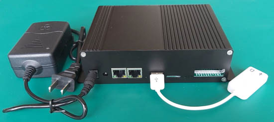
![]() The box has SD and USB host interfaces, and the USB can be connected to USB-Hub, USB sound card, USB disk, USB keyboard, USB232 serial cable and other equipment.
The box has SD and USB host interfaces, and the USB can be connected to USB-Hub, USB sound card, USB disk, USB keyboard, USB232 serial cable and other equipment.
![]() The box has 2 function buttons, 5 LED indicators, The combination of 5 LED lights flashing, on and off at different speeds can easily indicate the different states of the box, such as: DMX512 output mode, LED output mode, upgrade mode, startup mode, network cable access indication, network data indication, wifi Indication, fault indication…
The box has 2 function buttons, 5 LED indicators, The combination of 5 LED lights flashing, on and off at different speeds can easily indicate the different states of the box, such as: DMX512 output mode, LED output mode, upgrade mode, startup mode, network cable access indication, network data indication, wifi Indication, fault indication…
| No. | Property | Note | Remarks |
| 1 | power adapter | DC In: 7.5V~25V / 2A~1A | box power: 8W |
| 2 | DMX512 Output | 8 port of 250K standard DMX512 output, with optical signal and electrical signal isolation,each channel has an exclusive 16bit domain address, and each channel can independently set any port from 0 to 65535 | hardware with 3 DC-DC power isolation, 8 signal optical isolation |
| 3 | LED Output | 8 universe, 800K single-line output, timing compatible with WS281x chips | 2 output lines, each line outputs 4 universe, also compatible Madrix patch fixture with dmx512 mode |
| 4 | WiFi | 2.4G / 150Mb , can be set to open and close freely | start peak:800ma , working:120ma |
| 5 | LAN port | 2 port 10M/100Mb adaptive lan interface, programmable | LAN1 and SD card/PWM multiplexing, LAN1 and SD/PWM cannot be used at the same time, choose 1 of 2 |
| 6 | USB port | Host, can connect to most USB devices, special devices need us to write drivers | DC: 500ma output, with PTC protection |
| 7 | SD card | TF card, support any capacity | support FAT、FAT32、NTFS、EXT4 |
| 8 | button | 1 hard reset RST button (if pressed the box will reset and restart), 1 multi-function WPS button | WPS has 2 functions. If box Wifi is turned off, press and hold WPS for 5 seconds, wifi will be turned on, if you continue to hold for more than 20 seconds, the box will be restored to the factory settings |
| 9 | LED indicator | 5 LED lights, 2 green lights, 2 yellow lights, 1 red light | different combinations of flashing, on and off have different definitions |
| 10 | I2C | 1 port 100K/400K | have command line tools, easy script programming |
| 11 | infrared IR | 1 receiving, 1 transmitting (IO port mode) | can support more than 99% of infrared remote controls on the market, the box does not have a remote control, the remote control needs to be set (learned) before it can be used |
| 12 | PWM | 2 port: PWM0、PWM1 | GPIO multiplexing, with command line tools |
| 13 | UART | 3 port: UART0 for Linux, UART1/UART2 for general equipment | UART1/2 multiplexed with GPIO, TTL level, UART1 is 3.3V, UART2 is 5V, Not RS232, connect to RS232 will burn the main chip! |
| 14 | GPIO | 2 port | can reuse other function pins to release more GPIO |
| 15 | 3.3V/5V output | one 3.3V/ one 5V | 5V with PTC protection, limited to 500ma, 3.3V without protection, if the output power plus the total power of the box is greater than 8W, it will protect, So, please try not to use 3.3V to power external devices, because 3.3V consumes a lot of power |
attention please:
If you do not have professional knowledge, please do not easily connect items 10~15, because these pins are directly connected through the main CPU chip. The core working voltage of the CPU is 1.2V/1.8V, and the maximum voltage that the pins can withstand is 3.3V, if the external signal or power supply greater than 3.3V is connected by mistake, the CPU will be burned, If the CPU is burned, the box will basically be scrapped. Burned chips are not covered by the warranty.
The box will be sealed when leaving the factory, If you tear the seal, Will be deemed to automatically waive the warranty rights, Please pay attention to this clause.
Q2: Box LED light status description
The box has 5 LED lights. The combination of these 5 lights in different states indicates different working states of the box.
![]() 1 green light, 2 yellow light, 3 green light, 4 yellow light, 5 red light
1 green light, 2 yellow light, 3 green light, 4 yellow light, 5 red light
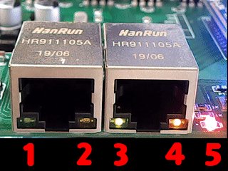
![]() The green light 1 is an indication of whether the LAN0 port is connected to the network cable, it will be on when the network cable is connected, and it will flash when there is network data.
The green light 1 is an indication of whether the LAN0 port is connected to the network cable, it will be on when the network cable is connected, and it will flash when there is network data.
![]() The green light 3 is the indication of the LAN1 port. It will be on when the network cable is connected, and it will flash when there is network data. In factory mode, it will flash together with 4 and 5 quickly.
The green light 3 is the indication of the LAN1 port. It will be on when the network cable is connected, and it will flash when there is network data. In factory mode, it will flash together with 4 and 5 quickly.
![]() yellow 2 and yellow 4 have multiple states: DMX512 output mode: yellow 2 will keep flashing, after 512 times, it will be off for 2 seconds, and yellow 4 will be on alway; LED output mode: yellow 2 will be on always, yellow 4 will keep flashing, after 512 times, it will be off for 2 seconds; If yellow 2 and yellow 4 flash alternately for a long time, it means that the box has a serious fault and cannot be repaired by itself, Please contact us.
yellow 2 and yellow 4 have multiple states: DMX512 output mode: yellow 2 will keep flashing, after 512 times, it will be off for 2 seconds, and yellow 4 will be on alway; LED output mode: yellow 2 will be on always, yellow 4 will keep flashing, after 512 times, it will be off for 2 seconds; If yellow 2 and yellow 4 flash alternately for a long time, it means that the box has a serious fault and cannot be repaired by itself, Please contact us.
![]() Red 5 status: Wifi connection will flash; startup will flash; upgrade will also flash; No matter what, it must be on or flash to be normal. When the box starts, you can watch red 5 from flashing to no longer flashing, yellow 2 or yellow 4 one of them will flash, one for always on, this status to indicate successful startup.
Red 5 status: Wifi connection will flash; startup will flash; upgrade will also flash; No matter what, it must be on or flash to be normal. When the box starts, you can watch red 5 from flashing to no longer flashing, yellow 2 or yellow 4 one of them will flash, one for always on, this status to indicate successful startup.
| Status | Green 1 | Yellow 2 | Green 3 | Yellow 4 | Red 5 | Note |
| DMX512 output start status | – | Long bright | – | Long bright | Flashing | Yellow 2, 4 will flash alternately once, the red 5 light will light up first and then flash |
| LED output start status | – | Long bright | – | Off | Flashing | Yellow 2, 4 will flash alternately once, the red 5 light will light up first and then flash |
| DMX512 control status | – | Flashing | – | Long bright | – | Red light is on or flashes occasionally (normal working state) |
| LED control status | – | Long bright | – | Flashing | – | Red light is on or flashes occasionally (normal working state) |
| LAN0 status | Flashing/Bright | – | – | – | – | Long light indicates that the network cable is normal, flashing means have network data |
| LAN1 status | – | – | Flashing | – | – | Flashing means that the access network cable is normal, have network data |
| Wifi status | – | – | – | – | Flashing/Bright | Connect wifi and have Wifi data will flash |
| Factory mode | – | – | Flashing | Flashing | Flashing | Please press the Rest button or unplug the power to reset once |
| Upgrade firmware mode | – | Stop flashing | – | Stop flashing | Flashing | Do not turn off the box power during the upgrade, the upgrade will take 3 minutes |
| Boot failure | – | – | – | – | No flashing/No light | The red light does not turn on or flash when box power on, Major failure, Please contact us |
| Unable to clear fault | – | Flashing alternately | – | Flashing alternately | – | Yellow 2 and 4 flashes alternately for a long time, the fault can’t be cleared, please contact us (see the picture below) |
Failure, unable to recover, please contact us
Q3: Description of the internal interface of the box
![]() When the box leaves the factory, Wifi uses a built-in antenna. If you want a longer transmission distance and a stronger signal, you can replace it with a 2.4G/4dB… or higher gain antenna. The antenna interface is IPX1 with a diameter of 2mm.
When the box leaves the factory, Wifi uses a built-in antenna. If you want a longer transmission distance and a stronger signal, you can replace it with a 2.4G/4dB… or higher gain antenna. The antenna interface is IPX1 with a diameter of 2mm.
![]() The light output interface uses a phoenix head, The DMX512 interface line sequence is in accordance with the DMX512 standard: 3+ 2- 1GND; The LED strip SPI control is a single-wire interface, each wire transmits 4 universe data, each wire can be connected to 680 RGB pixels, and a total of 1,360 3-channel RGB pixels can be controlled. The connection of universe will automatically be spliced internally by box, compatible with the Madrix patch fixture method.
The light output interface uses a phoenix head, The DMX512 interface line sequence is in accordance with the DMX512 standard: 3+ 2- 1GND; The LED strip SPI control is a single-wire interface, each wire transmits 4 universe data, each wire can be connected to 680 RGB pixels, and a total of 1,360 3-channel RGB pixels can be controlled. The connection of universe will automatically be spliced internally by box, compatible with the Madrix patch fixture method.
![]() DMX512 output and LED-SPI output can’t be used at the same time, can in webui switch to use via [BOX SETUP] -> “Lighting Out Mode”.
DMX512 output and LED-SPI output can’t be used at the same time, can in webui switch to use via [BOX SETUP] -> “Lighting Out Mode”.
![]() The box input power uses a wide voltage, DC 7.5V ~ 25V can be, if you use 7.5V, at least 2A or more, if you use 12V or more, at least 1A or more.
The box input power uses a wide voltage, DC 7.5V ~ 25V can be, if you use 7.5V, at least 2A or more, if you use 12V or more, at least 1A or more.
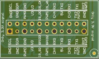
![]() Please note: GPIO DIP is the 10th to 15th interface in Table 1. If connected, it will be regarded as automatically waiving the warranty rights.
Please note: GPIO DIP is the 10th to 15th interface in Table 1. If connected, it will be regarded as automatically waiving the warranty rights.
The row of large holes outputs 5V signals, please do not connect it back to the box.
IR_SO is the infrared emission GPIO interface, which can connect the infrared emission line of the centralized control system Or the positive (long pin) of the IR transmitter tube is connected to this IO port, and the negative pin is connected to GND, you can use the “irsend” command to transmit infrared codes to control any external device with an infrared interface;
TX0 and RX0 only a ports for Linux log printing, used for debugging;
TX1, RX1 / TX2, RX2 are configurable UART communication ports, which can be connected to a 3.3V TTL serial port for communication. Note that it is not an RS232 interface, RS232 is a serial port with a level conversion chip, RS232 voltage is higher than +-13V, If RS232 is connected to box IO port, Box CPU chip will be burned. The external RS232 needs to cancel the level conversion chip to connect to the box IO port. TX2 and RX2 can also reuse pwm2 and pwm3;
SCL and SDA are I2C interfaces, which can communicate with external devices through the command line “i2c”;
GPIO2 and 3 are two IO ports that can be input or output;
pwm0 and pwm1 are 2 pwm outputs, which can be reuse with GPIO;
V3 and 5V are 3.3V power supply and 5V power supply, which can supply power to an external sensor. Note that the power is limited;
CH3 and CH4 are factory reserved functions.
Q4: How to test out of the box?
You can connect via Wifi or connect the network cable to the box LAN0 port, Connect the box to test.
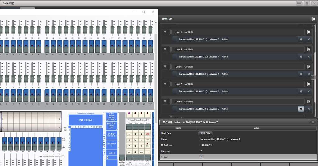
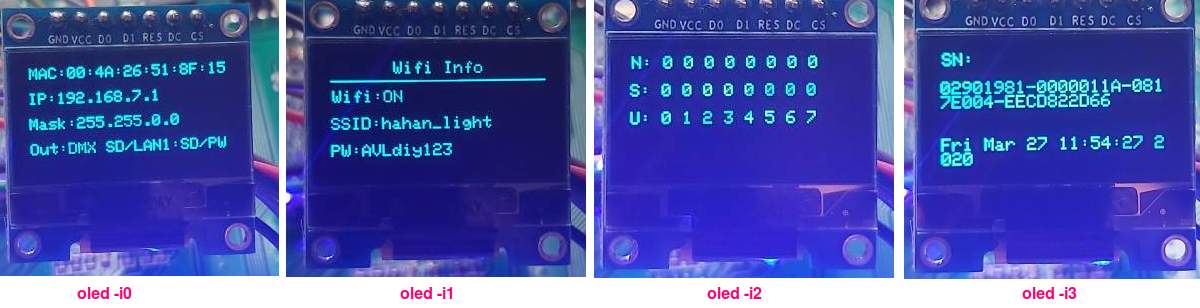
![]() Box out factory state: Wifi SSID: hahan_light / Wifi password: AVLdiy123 / IP: 192.168.7.1 / Mask:255.255.255.0 / root password: AVLdiy123.
Box out factory state: Wifi SSID: hahan_light / Wifi password: AVLdiy123 / IP: 192.168.7.1 / Mask:255.255.255.0 / root password: AVLdiy123.
Note: Connecting the box via Wifi does not need to set the computer IP address, The box Wifi is DHCP mode and will automatically assign an IP to the computer, but if the computer is connected to the LAN0 port through a network cable, you need to set the computer’s IP to 192.168.7.xx, because the factory setting of the box LAN port is static IP, the computer IP must be in the same network segment as the box to connect.
![]() After the box is connected to the light, open the browser of the computer or mobile phone, enter the IP address of the box: 192.168.7.1, connect to the box, you can set the box through webui, or you can control the actual light through the web console [Lighting Test],
After the box is connected to the light, open the browser of the computer or mobile phone, enter the IP address of the box: 192.168.7.1, connect to the box, you can set the box through webui, or you can control the actual light through the web console [Lighting Test],
You can check whether the light is controlled by pushing the [Lighting Test] fader.
“AutoTest” is a reciprocating switch, press it to automatically test, press it again to stop the test.
![]() PC computers can be tested through professional DMX software, such as running MAlighting official gramdMA2 onPC3.125 version with Artnet unlocking, or Madrix software, or Avolites Titan… through Artnet or sACN connected to the box for testing,
PC computers can be tested through professional DMX software, such as running MAlighting official gramdMA2 onPC3.125 version with Artnet unlocking, or Madrix software, or Avolites Titan… through Artnet or sACN connected to the box for testing,
The Artnet output setting method of these softwares, please google by yourself, you can search for many video teaching in youtube.
You can also use some VJ software to map the video to the light through the box.
Note that when using MA onPC, the computer IP must be set or a fixed IP of 2.0.0.x must be added.
Otherwise, the MA onPC will not output Artnet, because the standard Artnet protocol will poll 2.x.x.x as the main network and 10.x.x.x as the secondary network. The IP of the device is calculated by the MAC address of the network card, and the MAC is unique in the world, so any lighting device can join the Artnet network without an IP, The IP will not be repeated, You only need to fixed the IP of the Artnet server to 2 or 10 network segments, This is the original intention of the Artnet protocol design, The device can be plug and play without setting.
MA is based on artnet specifications, so 2 network segments must be set. Now many devices do not follow the specifications, this makes artnet messy, our box can ignore any IP things, because the box is a network processing protocol written by myself, and all data is processed in the second layer of the network protocol.
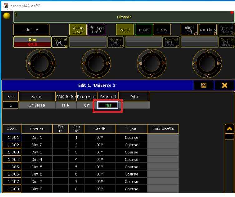
After Ma onPC is set correctly, if there is artnet output, the Universe Granted will display a green Yes. Note: You must patch the light fixture before setting Artnet, otherwise there will be no artnet output.
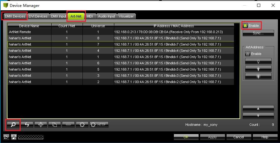
The setting method of Avolites Titan: In titan, right-click the AVO button, then left-click the Disk button to enter the system mode, click DMX settings from the menu on the right side of the screen, the DMX setting window will open, and you can see Artnet settings, and at the same time, “DMX Line” can be found to find our box “hahan’s Artnet”, now, add to universe 0-7, as shown in the figure above.
Please note: The box can support Artnet and sACN protocols at the same time. Do not enable these two protocols in titan at the same time. Please choose 1 of 2 protocols, otherwise, The same data will be sent to our box at the same time through these two protocols, Not only wastes network bandwidth, Also doing useless work, even, Because data overlay may cause minor effects that cannot be detected.
The setting method of Madrix: Press the F4 key on the keyboard in Madrix, the picture above appears, click the magnifying glass icon in the lower left corner to find our box, and then click the “DMX Devices” in the upper left corner to output all “On”, Madrix will output Artnet Data to our box.
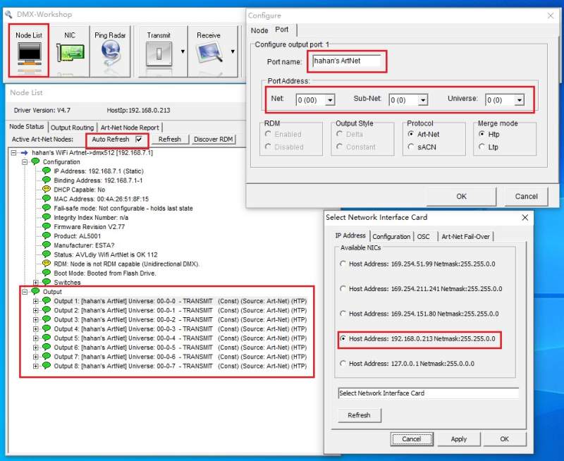
![]() Or the computer runs the Artnet protocol testing software Bwtest or DMX-Workshop for testing. It should be noted that the latest version of Bwtest/DMX-Workshop must be used to support the latest Artnet1.4 protocol, The old version software does not support 15bit address, so old version software will not find our box.
Or the computer runs the Artnet protocol testing software Bwtest or DMX-Workshop for testing. It should be noted that the latest version of Bwtest/DMX-Workshop must be used to support the latest Artnet1.4 protocol, The old version software does not support 15bit address, so old version software will not find our box.
![]() The box supports a lot of professional software, For other latest professional DMX software, please visit our website http://www.AVLdiy.cn to get the latest patch to support box output. The use of patch is so easy, that is, copy our dll file to the installation directory of the control software, without any settings, now connect to our box, You can control the lighting through the software and our box. For the specific method, please refer to the description of the readme of each catalog.
The box supports a lot of professional software, For other latest professional DMX software, please visit our website http://www.AVLdiy.cn to get the latest patch to support box output. The use of patch is so easy, that is, copy our dll file to the installation directory of the control software, without any settings, now connect to our box, You can control the lighting through the software and our box. For the specific method, please refer to the description of the readme of each catalog.
Note: Different software has different line output numbers. For example, grandMA2 onPC has 256 universe output, madrix has 256 universe, sunlite3 has 50 universe, daslight4 and mydmx3 have 40 universe outputs, and cueluxpro has 70 universe output… , our one box has 8 universe of hardware output, You can combine N multiple boxes to expand the output line through the network cable, our box has 2 LAN ports, and the boxes can be cascaded hand in hand through the network cable, Does not need any switch or router, the box has switching and routing functions.
There are also some old software that only output 4 universe, such as Martin’s classic lightjockey software, free version of M-PC, onyx, etc. If you connect the box with threse software, the box will have 4 universe free, and the 4 free universe of the box can also be set to the same for use universe, do this can be use output backup.
Please note: What is the universe of the box seted then which universe is the software output.
Even if you only have one box, you can set the universe to 255, then you only need to patch lighting fixture library to 255 in the software, and program lighting show in the universe 255, then lighting show will output to the box 255 universe.
If you are happy, the 8 universe of the box can also be set to be like this: 8, 127, 24, 111, 222… some messy numbers, only need to program lighting show in these universe of the software, and the software lighting show will be out to our box same universe.
Q5: How to play offline files?
1:You can play by clicking the mouse in [OFFLINE PLAY] through the webui graphical interface -(Simple way)
![]() The multimedia files that the box can play support: AVI, MPG, WMV, JPG, BMP, GIF, WAV, MP3, FLAC, APE and our dedicated DMX and l3a files. If the mp4 file is decoded with H264/5, it will be too CPU, So only audio is decoded, images are not decoded. Note that the image of the video file is not out an external monitor, it is directly mapped to the light through the 8 output ports of the box, If there is a large area of LED light, it can be used as a screen.
The multimedia files that the box can play support: AVI, MPG, WMV, JPG, BMP, GIF, WAV, MP3, FLAC, APE and our dedicated DMX and l3a files. If the mp4 file is decoded with H264/5, it will be too CPU, So only audio is decoded, images are not decoded. Note that the image of the video file is not out an external monitor, it is directly mapped to the light through the 8 output ports of the box, If there is a large area of LED light, it can be used as a screen.
![]() Specific method:
Specific method:
Offline files can be saved to an SD card or USB disk. First create a “light” directory on the SD card or USB disk, and copy the multimedia files to this directory, Do not put file in other directories, because webui will only search for “light” directory, will not search other directories.
SD card and USB disk can be used at the same time, webui will display 140 files in [OFFLINE PLAY], 70 on the left are for SD card, and 70 on the right are for USB disk.
If only SD or USB disk is inserted separately, it will be displayed 140 files by inserted device, the upper right corner of [OFFLINE PLAY] will display the status of inserting SD/USB.
Note: Because SD and LAN1 are reuse, if you use SD card, you must select [Use Sd card] in [BOX SETUP], If you don’t set it, the data read out from SD card will be wrong.
It should be noted that our box does not support Chinese file names.
![]() In [OFFLINE PLAY] you can click the file name to play. The buttons are: previous track, stop, next track, play all tracks in the background, and pause; column 2: loop times, “FOLLOW”, “GAMMA”, volume fader.
In [OFFLINE PLAY] you can click the file name to play. The buttons are: previous track, stop, next track, play all tracks in the background, and pause; column 2: loop times, “FOLLOW”, “GAMMA”, volume fader.
“Play All” is to play all tracks in the background, after clicking this button, the player will play all multimedia files in the background, You can close the webui without affecting the playback.
“FOLLOW” checked means that after playing a file in webui, the next file will be played automatically.
“GAMMA” is only for video files, Checked means that GAMMA will correct the video, which is invalid for audio and DMX files.
Note: If you close webui for any non-background playback, our box will automatically stop playing after playing the current track.
2:Run our special software [lightplay -l0 -g0 -r30 “filename.dmx”] through the command line to play -(Advanced Way)
![]() Lightplay can take 4 parameters, the file name to be played cannot be less, but other 3 parameters can be omitted. For example, you can directly enter the command line [lightplay “file name.avi”] to play. the file name can have an absolute path, If you are connected to the Internet, you can also bring an Internet address.
Lightplay can take 4 parameters, the file name to be played cannot be less, but other 3 parameters can be omitted. For example, you can directly enter the command line [lightplay “file name.avi”] to play. the file name can have an absolute path, If you are connected to the Internet, you can also bring an Internet address.
The parameter “-l” can be followed by the number of loops to be played, l is shorthand for loop;
“-r” can be followed by the playback rate of DMX512, This parameter is only for DMX files. The standard DMX512 generally rate is 30ms/33Hz, if changing this value, you can slow or fast play DMX files; “-g” can be followed by 0 Or 1, g is shorthand for gamma, 0 means no gamma correction, 1 means gamma correction will be performed, The mapping of video files to lights generally requires gamma correction, because the change in light brightness is not linear, but logarithmic, If there is no gamma correction, the brightness will not be turned off. but not video files generally do not need to be corrected.
![]() The key point is to talk about DMX files and l3a files, DMX files are captured by “Catch” in [OFFLINE PLAY]. Whether it is a physical console or DMX software, or simulator, it can be connected to our box through the network (such as Artnet or sACN), and the light show data played by the console will eventually be transmitted to our box, so show data can be captured into a DMX file through webui’s catch , In this way, you can clone the entire light show of the console, and then play this DMX file through the box of offline function.
The key point is to talk about DMX files and l3a files, DMX files are captured by “Catch” in [OFFLINE PLAY]. Whether it is a physical console or DMX software, or simulator, it can be connected to our box through the network (such as Artnet or sACN), and the light show data played by the console will eventually be transmitted to our box, so show data can be captured into a DMX file through webui’s catch , In this way, you can clone the entire light show of the console, and then play this DMX file through the box of offline function.
l3a is a playlist file, which is actually a text file. You can record different multimedia file names and DMX file names into this l3a file according to your own ideas and playback order, and then use the command line “lightplay xxx.l3a” to play this list. There is a simple way to generate the l3a file in the linux shell, You can redirect all multimedia files to the file through the listed directory to generate: “ls> demo.l3a” This will generate the demo.l3a file for all the files in the current directory.
![]() There are some lighting shows that require music to be synchronized, but the captured DMX files are pure lighting data and there is no audio, What should I do?
There are some lighting shows that require music to be synchronized, but the captured DMX files are pure lighting data and there is no audio, What should I do?
There is a very simple trick, just change the music file to the same file name as the DMX file, put it in the same directory and you can play it simultaneously.
For example: we captured a file called demo.dmx, this show synchronizes a song called fade.wav, just change fade.wav to demo.wav, and then put it in the same directory as demo.dmx, command line Enter [lightplay demo.dmx ], the box will play dmx files and wav files at the same time, and it can be synchronized with sound and light when offline.
![]() Finally, if you want to hear the sound, don’t forget to insert the USB sound card into the USB port of the box. The box USB interface supports most of the USB sound cards, from the 6 yuan Taobao kind to my thousands of professional sound cards have been tested.
Finally, if you want to hear the sound, don’t forget to insert the USB sound card into the USB port of the box. The box USB interface supports most of the USB sound cards, from the 6 yuan Taobao kind to my thousands of professional sound cards have been tested.
Q6: How to capture DMX files?
1:Through the webui graphical interface, click [OFFLINE PLAY]->Catch to capture -(Simple way)
![]() First select a place to save the captured file, “SD card or USB disk”, and then enter the name of the file you want to save. If you don’t enter it, the default name is “DEMO”.
First select a place to save the captured file, “SD card or USB disk”, and then enter the name of the file you want to save. If you don’t enter it, the default name is “DEMO”.
“Rate” is the frame rate of capturing DMX512, which is a time unit of ms. The larger the HZ, the larger the captured file, generally 30ms/33Hz (capture 33 frames in 1 second), The default frame rate of Madrix is this. If you don’t understand what the meaning of rate, it is best not to change it, just use the default value.
After pressing “Catch”, the file name will automatically add a number, and then save it to the “light” directory of SD card or USB. After captured, you can refresh it directly, it will appear in the list of [OFFLINE], you can click file name to play to see the effect, If you are not satisfied, you can capture again, After clicking “Catch”, the file name will automatically add 1 to save.
2:Run our special software [catchlight -r30 “filename.dmx”] through the command line to capture -(Advanced Way)
![]() catchlight can take 2 parameters, the file name must not be less, the -r parameter can be omitted, for example, you can directly enter the command line [catchlight demo.dmx] to capture, The default frame rate is 30ms/33Hz.
catchlight can take 2 parameters, the file name must not be less, the -r parameter can be omitted, for example, you can directly enter the command line [catchlight demo.dmx] to capture, The default frame rate is 30ms/33Hz.
![]() It should be noted that the lighting effects are edited in the lighting console or control software, and the capture is real-time, It is what lighting effect the console is currently outputting and what effect is captured. If the console does not output any lighting effects, the capture data is 0. Note that 0 will also occupy the storage space, not empty.
It should be noted that the lighting effects are edited in the lighting console or control software, and the capture is real-time, It is what lighting effect the console is currently outputting and what effect is captured. If the console does not output any lighting effects, the capture data is 0. Note that 0 will also occupy the storage space, not empty.
Q7: How to make a video offline file by yourself?
![]() An advanced function of the box is that it can be mapped to the light by playing video, so it can achieve offline function by making video files by yourself. Video files can also add audio, which can synchronize lighting by sound and video. Video files can be produced by professional video editing software, There are many such software, such as AE, Vegas… / Kdenlive of linux…
An advanced function of the box is that it can be mapped to the light by playing video, so it can achieve offline function by making video files by yourself. Video files can also add audio, which can synchronize lighting by sound and video. Video files can be produced by professional video editing software, There are many such software, such as AE, Vegas… / Kdenlive of linux…
![]() It should be noted that the box has only 8 universe of output and can control 1360 RGB pixels, so the edited video file cannot be larger than this pixel size, and the video must be the same as the actual lighting patch layout. Video is scanned line by line, so the lighting patch layout also needs to be equipped with the video scanning method. Or when making a video file, the size of the video is determined according to the layout of the actual lighting.
It should be noted that the box has only 8 universe of output and can control 1360 RGB pixels, so the edited video file cannot be larger than this pixel size, and the video must be the same as the actual lighting patch layout. Video is scanned line by line, so the lighting patch layout also needs to be equipped with the video scanning method. Or when making a video file, the size of the video is determined according to the layout of the actual lighting.
Q8: How to login to the box by root?
-
- It should be noted that the root operation under the linux system is destructive. If you delete the system files by mistake, the box may not start and you must return box to the factory for repair, This repair is not covered by the warranty. Therefore, without understanding linux system, Please don’t try login the box by root.
![]() You can log in to the box through SSH software, Commonly used SSH software are: PuTTY, WinSCP, Telnet…, run one of the software, enter the box’s IP: 192.168.7.1, user name: root, password: AVLdiy123, you can log in to the box. After the login is successful, you can operate the box, such as uploading, downloading files, entering command lines in the shell, writing scripts for secondary development and so on.
You can log in to the box through SSH software, Commonly used SSH software are: PuTTY, WinSCP, Telnet…, run one of the software, enter the box’s IP: 192.168.7.1, user name: root, password: AVLdiy123, you can log in to the box. After the login is successful, you can operate the box, such as uploading, downloading files, entering command lines in the shell, writing scripts for secondary development and so on.
![]() There is a simple method in webui, without any software, you can log in to the box through a browser. Click [ADVANCED], after confirming the agreement, you can log in to the box.
There is a simple method in webui, without any software, you can log in to the box through a browser. Click [ADVANCED], after confirming the agreement, you can log in to the box.
![]() Note: If you use scripting for secondary development, you must log in to the box to perform secondary development. And you need to understand some linux commands and basic linux operations, If you want more advanced, you also need to understand the syntax and writing rules of scripts.
Note: If you use scripting for secondary development, you must log in to the box to perform secondary development. And you need to understand some linux commands and basic linux operations, If you want more advanced, you also need to understand the syntax and writing rules of scripts.
Q9: some commonly used tool software
![]() light is a lighting control command line program, which can read, write, and set the DMX value of each port. The format is “light [0..8] [r/w/s] [channel] [data] “, The parameters [0..8] is the box output ports U0~U7 and all, 0~7 correspond to the device file “/dev/light0~light7”, where 8 means all output 4096 channels, corresponding to the device file “/dev/light_all”.
light is a lighting control command line program, which can read, write, and set the DMX value of each port. The format is “light [0..8] [r/w/s] [channel] [data] “, The parameters [0..8] is the box output ports U0~U7 and all, 0~7 correspond to the device file “/dev/light0~light7”, where 8 means all output 4096 channels, corresponding to the device file “/dev/light_all”.
There is an important concept in linux: “Everything is a file!”, text data is file, audio and video are stored in multimedia files, and hardware devices are also files, You are not mistaken! Hardware is also a file, Like text files, you can open, read, write, close and other operations. You can see all hardware devices file in the “/dev/” directory.
[r/w/s] are read, write and set, “s” is batch setting, For example, “light 7 s 100 120” means to set U7 in batches, from 100 to 512 channels, the value is 120, “s” is followed by which channel will start, and will continue to the end of all channels, no need to fill in the end channel, DMX512 output channels The default is 512/4096, and LED output channels the default is 510/4080.
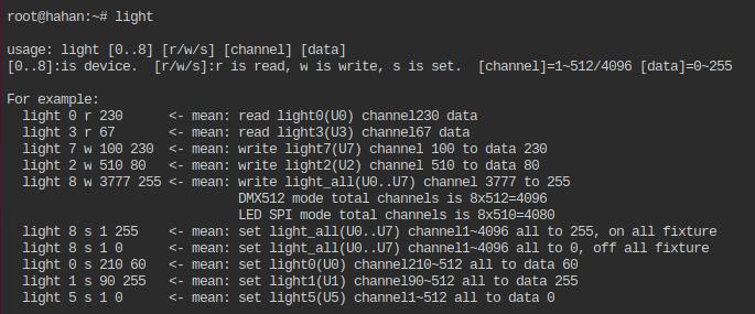
Light software can also read the DMX value of a each channel of any output port. For example, to read the DMX value of PORT2 channel 500, you can enter: [light 2 r 500], the screen will print the dmx512 value of U2 channel 500.
Suppose we need to control an external device or play a song or play offline files through U2 channel 500, The dmx value of the channel not only can control the dmx512 lighting, but also can control the device itself, The external dmx512 device can be a physical console or software or other network devices, only need writing a linux shell script can do it.
#!/bin/sh
while true
do
val=light 2 r 500
if [ $val = 200 ]
then
lightplay fade.wav #play song or do something
exit
fi
sleep 2
done
Seeing these codes is a bit dizzy, this is an advanced function, you need to understand the writing rules of the shell to understand, but don’t be afraid of it, the shell syntax is very simple, google has a lot of teaching, The core of the shell is just one sentence: if the value of U2 channel 500 is 200 then “lightplay fade.wav”, will play the song of fade.wav, If it is other value, it will be checked every 2 seconds, and it will exit until the detection is successful.
![]() There is also a program readlight for reading light dmx values. The difference between readlight and light is: that ‘light’ can read or set the value of each channel, ‘light’ reads the value set by itself, not external Artnet, sACN… . transmitted from the network value;
There is also a program readlight for reading light dmx values. The difference between readlight and light is: that ‘light’ can read or set the value of each channel, ‘light’ reads the value set by itself, not external Artnet, sACN… . transmitted from the network value;
readlight only read the dmx value, cannot set the channel value. ‘readlight’ reads the value from the external Artnet, sACN… from networks, ‘readlight’ can be triggered through the external console to call the internal functions of the box.
readlight usage is as follows:
root@hahan:~# readlight -h
Copyright(c) by AVLdiy.cn / hahan”
usage: readlight -p1 -c100 -r20 -x -h
-p: universe port number, 0~7 is box port ‘/dev/light0~7’, 8 for ‘/dev/light_all’, default is port0
-c: which channel do you want to be read, it’s a channel address, default is 1
-r: how many channels do you want read, it’s a read count number, defaul is 1
-x: show mode, if add -x then show Hexadecimal, default show Decimal
-h: help
“-p”followed by the output ports 0~7 that need to be read, If it is 8, it means all output ports, defaults to port 0;
“-c”channel address 1~512, which channel needs to be read, then fill in the value of that channel, the box defaults to 1, if the -p8 parameter is added, the channel address range is: 1~4096;
“-r”followed by how many channels need to be read, default is 1 channel;
“-x”displays decimal or hexadecimal, the default is decimal, add -x to display hexadecimal, no parameter value
“-h”help, -h has no parameter value
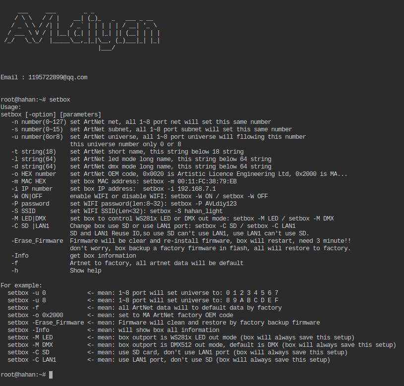
![]() setbox can be regarded as a command line program of webui. Setbox can set and change the parameters of the box, can also set the lighting protocol parameters, and can also view the information of the box. setbox has a “-o” parameter, which can change the Artnet OEM value of the box, so that the box becomes a product of a different manufacturer, such as MA, Artistic or Madrix products… This value can be checked on the artnet official website. See the figure below for the specific usage of setbox.
setbox can be regarded as a command line program of webui. Setbox can set and change the parameters of the box, can also set the lighting protocol parameters, and can also view the information of the box. setbox has a “-o” parameter, which can change the Artnet OEM value of the box, so that the box becomes a product of a different manufacturer, such as MA, Artistic or Madrix products… This value can be checked on the artnet official website. See the figure below for the specific usage of setbox.
Q10: How to use infrared remote control?
![]() The box can support more than 99% of the remote controllers with different protocol formats, can support the “lirc, rc-5, rc-5-sz, jvc, sony, nec, sanyo, mce_kbd, rc-6, sharp, xmp” protocol, only need through infrared learning, catch the infrared code then can be used.
The box can support more than 99% of the remote controllers with different protocol formats, can support the “lirc, rc-5, rc-5-sz, jvc, sony, nec, sanyo, mce_kbd, rc-6, sharp, xmp” protocol, only need through infrared learning, catch the infrared code then can be used.
![]() We have developed some IR software such as readir, irset and irsend. readir is a set of commonly used programs, the format is [readir -g5000 -t1 -p nec], the three parameters can also be ignore, -g means gap, followed by a time, which is a ms time, after running readir with the parameter g , If no infrared data is received, it will exit after -g microseconds, the default is 3000 (3 seconds); if g is followed by -1, it will always wait for the infrared key press, after receiving the infrared key press value, readir will print hexadecimal of the key value and then exit. If the infrared key has not been received, it will wait forever and will not exit;
We have developed some IR software such as readir, irset and irsend. readir is a set of commonly used programs, the format is [readir -g5000 -t1 -p nec], the three parameters can also be ignore, -g means gap, followed by a time, which is a ms time, after running readir with the parameter g , If no infrared data is received, it will exit after -g microseconds, the default is 3000 (3 seconds); if g is followed by -1, it will always wait for the infrared key press, after receiving the infrared key press value, readir will print hexadecimal of the key value and then exit. If the infrared key has not been received, it will wait forever and will not exit;
-t can be followed by 1 or 0, which means test. 1 means to enter the test learning mode, and the readir software will not exit unless you manually press “CTRL+C” to exit. This is mainly used to learn infrared codes, such as running [readir -t1] After pressing the key of the remote control, readir will print out the key value please remember this value, We need to use these key values to make a configuration file, This configuration file will be automatically loaded when linux is started, then can use this remote control directly.
-p is followed by the remote control protocol. different remote control manufacturers have different remote control protocols, nec and rc5 protocols are commonly used. The -p parameter is generally not used, all protocols are loaded by default. The function of -p can confirm the specific protocol when the remote control is learning. For example: Assuming that [readir -t1] can read the key value of the remote control, but [readir -p rc5] cannot read it, it means that the remote control is not rc5, You can confirm the protocol of the remote control by excluding it several times. Generally, it is in nec format, we need know remote protocol format to make configuration files by yourself.
![]() How to make a key-value configuration file?
How to make a key-value configuration file?
1:The box defines 9 key functions, which the “V” and “left arrow” keys are defined as the previous track function; the “N” and “right arrow” keys are used as the next track function; the “up arrow” key is used as the volume Increase function; “Down arrow” key is used as volume decrease function; “P” key and “Space” key are used as pause function; “Q” key is used as exit function.
2:The infrared remote control only needs to make a key value correspondence table, and the buttons on the remote control correspond to 9 functions then can used the infrared remote control. This table is in “/etc/rc_keymaps/default_ir.toml”, you can edit this file, modify the key values of the infrared remote control one by one.
3:The key value of the infrared remote control can be learned through [readir -t1], do not modify the format of the default_ir.toml file casually,
Just change the protocol = “nec” to the protocol of your own remote control, and then change the corresponding remote control key value to the corresponding function you want, like to the following table:
[[protocols]]
name = “default_ir”
protocol = “nec”
[protocols.scancodes]
0xef00 = “KEY_UP”
0xef01 = “KEY_DOWN”
0xef02 = “KEY_Q”
0xef03 = “KEY_P”
0xef0b = “KEY_V”
0xef0f = “KEY_N”
0xef15 = “KEY_LEFT”
0xef16 = “KEY_RIGHT”
…
0xef00, 0xef01, 0xef02… These key values are learned through [readir -t1]. after editing the configuration file, you need to restart the box. After startup, you can run [irset -r] to test whether it is correct, If it displays something like “scancode 0xef00 = KEY_UP (0x67)…”, it means the setting is correct.
Suppose the box U4 is connected to a DMX512 lighting, channel 100 is the brightness of the light, and there have an air conditioner, the remote control key value of the air conditioner is 0x87FE/nec format, I have a remote control, the W button of my remote control key value is 0xef07, If I want to press the W key to turn on the air conditioner and open lighting to on, then can write a script to do it. (# is a comment and will not be executed, the content after # will be ignored when the script is executed):
#!/bin/sh
while true #Keep looping the following content
do
val=readir #Read infrared remote control value
if [ $val = 0xef07 ] #If read a value of w pressed (W pressed is detected)
then
light 4 w 100 255 #Push U4 channel 100 to 255 and lighting on
irsend -S nec:0x87fe #Send the infrared start key value to the air conditioner, like pressing the power button of the air conditioner remote control
exit #exit
fi
sleep 2 #if not detected, delay 2 seconds, then continue to loop
done
There is an irsend on the 8th line above. The main function of irsend is: the box sends infrared codes to the outside. The box have a GPIO pins for infrared emission, but it does not connect to the infrared emission tube, so it needs to be connected to the infrared emission line for the centralized control system, or link a infrared emission tube yourself (Chinese Taobao is about 0.1 yuan).
irsend can send values in different protocol formats, as well as RAW values, -s (lowercase) is to send RAW values, and -S (uppercase) is to send values in protocol format.
irsend has a -r parameter, which will receive the RAW pulse value of the remote control, which can easily detect whether the remote control is normal. After running [irsend -r], press the remote control key, and some pulse data will be printed on the screen, If it is not printed, It means that there is either a problem with the remote control or a problem with the box receiving. If the remote control is very biased and the protocol is unknown, you can also send these RAW values directly to control the device.
The above script is assumed to be saved as a file named “ir_demo.sh”. This file cannot be run yet. You need to give this file an executable permission through the “chmod” command to run. Method: enter the command line “chmod 777 ir_demo.sh”, Now you can directly enter “./ir_demo.sh” to run this script.
Note: Unlike windows, linux system does not use a suffix to confirm whether a file is a execute program. Linux uses permissions to confirm whether a file is a execute program. If a notepad file is given the permission to run, the text file can be run as well, the script means this. and it can also be understood as the batch file bat of windows.
What should I do when box turned on can automatically run the “ir_demo.sh” script ?
Just edit the startup file “/etc/rc.local”, add the script “/etc/ir_demo.sh” into rc.local file before “exit 0”, then everything in this startup file will be automatically run when the box starts .
Q11: How to communication through serial port and box?
![]() Method 1: The external device communicates with the box serial port 1 and serial port 2 through the 3.3V/TTL level serial port. Note: Serial port 2 can be connected to 5V/TTL level.
Method 1: The external device communicates with the box serial port 1 and serial port 2 through the 3.3V/TTL level serial port. Note: Serial port 2 can be connected to 5V/TTL level.
There are 3 serial ports on the box board, among which serial port 0 is reserved for linux debugging, serial port 1 and serial port 2 can communicate with external devices. It must be noted that the on-board serial ports 0, 1, and 2 are 3.3V TTL levels. There is no RS232 level conversion chip, and it cannot be directly connected to the RS232 serial port. The external RS232 serial port needs to remove the level conversion chip to connect to our box, otherwise Will burn the main chip of our box.
Or directly connect to the 3.3V/TTL serial port, most of the serial ports of the sensor modules and the MCU serial ports are 3.3V/TTL level.
![]() Method 2: Connect box USB through the USB to RS232 serial cable, and convert it to RS232 serial port to communicate with external devices.
Method 2: Connect box USB through the USB to RS232 serial cable, and convert it to RS232 serial port to communicate with external devices.
Our box driver supports most USB to 232 chips on the market, including: CH341, FTDI, CP210x, pl2303, etc.
Note: these drivers are not installed when the box leaves the factory. You need to download the driver of the chip from our website to install it according to the chip model of your own serial cable. The installation method is very simple, just enter a command, if the box is connected to the network , Can also be installed online. The installation and uninstallation method of the box software will be introduced later.
![]() If the serial port is connected, you can use our [uart] program for serial communication. The uart program is powerful and it is a full-featured command line serial port debugging assistant. It took us a lot of time to write this program. There are as many as 13 parameters, but don’t be afraid. Many parameters can be defaulted. The format is as follows: (uart -f -b -d -e -s -w -r -g -t -c -n -x -h], the order of these parameters can be arbitrary, there is no order, and the values following the parameters can be separated by spaces You can directly follow the parameter value without adding spaces.
If the serial port is connected, you can use our [uart] program for serial communication. The uart program is powerful and it is a full-featured command line serial port debugging assistant. It took us a lot of time to write this program. There are as many as 13 parameters, but don’t be afraid. Many parameters can be defaulted. The format is as follows: (uart -f -b -d -e -s -w -r -g -t -c -n -x -h], the order of these parameters can be arbitrary, there is no order, and the values following the parameters can be separated by spaces You can directly follow the parameter value without adding spaces.
“-f” is followed by the device file name, for example, serial port 1 is “/dev/ttyS1”, serial port 2 is “/dev/ttyS2”, and USB to serial port is “/dev/ttyUSB0”, if you don’t add the -f parameter, the default is serial port 1 “/dev/ttyS1”;
“-b” is the baud rate, commonly used are “2400, 4800, 9600, 57600, 115200, 230400, 460800”, without the “-b” parameter, the box defaults to “57600”;
“-d” is data width, mostly 8bit, special equipment has 5, 6, 7 bits, generally 8bit, the box default is also 8bit;
“-e” is the parity bit, “O” is odd parity, “E” is even parity, “N” is no parity, the box defaults to no parity;
“-s” is a stop bit, usually 1 stop bit, but also 2 stop bits. For example, DMX512 has 2 stop bits, and the box defaults to 1 stop bit;
“-w” write data through the serial port, followed by some values that you want to send to the device. If there are spaces or some special symbols in the sent characters, you need to enclose them with double “” or single ”;
“-r” what follows is the number of characters that need to be read from the serial port. The read operation will block the thread until the specified number is read. The maximum number of bytes that a packet can read is 256. If you don’t want to be blocked, you can use it with the “-g” parameter;
“-g” it is the time interval, which is a time in ms, the minimum is 100ms, and the maximum is 25s. If you add this parameter, it means that the timing will be started after the first character is received, within the specified time, it will exit regardless of whether it receives a character or not. The default is 0ms, no delay. The combination of -g and -r can easily analyze the serial port protocol, For example, if you know that the protocol is 4 bytes, you can read it through “-r4 -g1000”, If you can’t read it within 1s, it will exit and timeout deal with;
“-t” it is the delay time of repeated transmission, a time with ms as the time unit, the default is 0ms;
“-c” the number of repetitions sent, if the -t parameter is added, it will be sent out repeatedly every time -t. by default, it will not repeat and only send once;
“-n” the input is in standard mode or non-standard mode, in standard mode, you need to press Enter key, then serial port will receive and return, in non-standard mode, input will receive then return, not check Enter key. The default is non-standard mode, this parameter has no parameter value;
“-x” Indicates that both sending and receiving are hexadecimal values. This parameter has no parameter value;
“-h” Indicates that information will be displayed. This parameter has no parameter value.
example:
1: uart -g 5000 //The parameter is the default: after reading the serial port 1, the baud rate is 57600 8N 1, 5000ms, if no value is read, it will exit, and if many characters are read within 5s, it will be printed out
2: uart -w123456dfcddw //Send the characters “123456dfcddw” to the default serial port 1, baud rate 57600 8N 1,
3: uart -w”this is a demo” -t500 -c100 //To the default serial port 1, the baud rate is 57600 8N 1, “this is a demo” is sent 100 times every 500ms
4: uart -w0xAA -c200 -x //Send 200 hexadecimal 0xAA to the default serial port 1, baud rate 57600 8N 1
5: uart -f/dev/ttyUSB0 -b 115200 -d8 -eN s1 -w’0x47 0x88′ -r2 -x //set the baud rate 115200 8N1 to the USB to RS232 serial cable, and send the hexadecimal “0x47 0x88″ at the same time, send over then wait for read 2 hexadecimal values of return form the device (assuming 2 bytes are returned) . Note: the parameter value can be separated by a space after the parameter, or not, for example, -b 115200 is separated by a space, -d8 is not separated, -w’0x47 0x88′ because there is a space between the 2 bytes, you need to use it Single” or double “” enclosed.
6: uart -f”/dev/ttyS2” -r7 //The default is 57600 8N 1. Blocking the read serial port 2, after reading 7 bytes, it will exit and print out 7 bytes. If 7 bytes are not read, it will wait until 7 bytes are read then exit.
7: uart -f/dev/ttyS2 -r7 -g3000 //The default is 57600 8N 1, blocking the read serial port 2. If 1 byte is read, the timing will be started, regardless of whether other values are read later, it will exit after 3 seconds. If 1 byte is not read, it will keep blocking until at least 1 byte is read.
8: uart -r2 -n //The parameter is the default: read serial port 1, baud rate 57600 8N 1. To read 2 characters in standard input mode, you must press Enter, otherwise it will not exit no matter how many characters are entered, and will eventually end with Enter.
9: Send custom commands through the external serial port to call the box’s lighting program or control some operations of the box:
#!/bin/sh
while true #Keep looping the following content
do
val=uart -r2 -g2000 #Read 2 characters from serial port 1
case $val in
01) callplay ‘/mnt/sda1/01.dmx’ #receive character 01 from outside device, then play the offline file “01.dmx” of the USB disk
;;
02) lightplay ‘/mnt/sda1/02.dmx’ & #receive character 02 from outside device, then play the offline file “02.dmx” of the USB disk
;;
03) callplay ‘/mnt/sda1/fade.avi’ #receive the character 03 from out device, play video file “fade.avi” and dim the brightness🔅 of the light at the same time
light 0 w 1 127
;;
44) light 8 s 1 0 #receive the character 44 from out device, turns off all lights, and exits the script at the same time
exit 1 #exits the script
;;
esac
sleep 2 #The external serial port sends other values, ignore it directly, delay 2 seconds, and then continue to loop to check the serial port
done
The functions of callplay and lightplay above are the same. They are both programs for playing files. The only difference is: callplay will check if there is a playing program running, if so, it will close the program, and then play the current file; lightplay It will not check whether there is a playback program running, and if there is, it will not close the file being played, so the current file will not be played.
Q12: How to use PWM?
![]() The box has 4 channels of PWM, among which PWM2, 3 and UART2 are multiplexed. If you use PWM, you cannot use LAN1, because if you use LAN1, the IO port will be multiplexed into an analog signal, not a digital interface.
The box has 4 channels of PWM, among which PWM2, 3 and UART2 are multiplexed. If you use PWM, you cannot use LAN1, because if you use LAN1, the IO port will be multiplexed into an analog signal, not a digital interface.
What can PWM do? PWM can control the rotation💞 of the motor at different speeds. For example, the motor in the Intelligent lighting is controlled by pwm; pwm can control the brightness of the screen; pwm can control the change of LED lighting; pwm can control the size of the power supply, etc…
We have written special drivers for PWM0 and PWM1 of the box, and we have also written user programs to facilitate users to control PWM through the command line. The pwm command-line program is also very powerful, with as many as 11 parameters. For specific usage, please see the English introduction in the following figure:
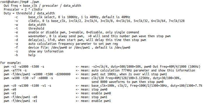
The output frequency of pwm = clk / prescaler / data_width;
prescaler = 2 ^ clkdiv (2 to the power of n);
duty = threshold / data_width , is how much time the high level takes
There are 2 types of pwm clock clk of the box, one is 100K, the other is 40M, which can be changed by -c parameter, -c0 is 100K, -c1 is 40M, the default is 40M;
We developed a personalized parameter-a for the pwm program, just need to follow the frequency that you want to output, the program will automatically calculate the parameter value of pwm for setting, we don’t need to calculate it by ourselves, but because the value of the approximation calculation will be certain Minor errors need to be noted.
Enter the following command:
1:pwm -v2 -w1000 -t200 -s //Frequency division factor 2 (prescaler=2^2=4), data width 1000, output frequency = 40000000/4/1000 = 10000Hz, duty = 200/1000 = 20% ;
2:pwm -f/dev/pwm1 -a7776 -s //-a is a square wave with 50% duty cycle automatically set, -f is the device name of pwm, and -s will display information. Command meaning: pwm1 automatically outputs frequency 7776Hz.
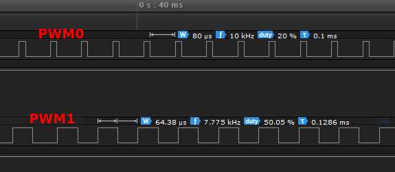
Connect the oscilloscope, you can see that the boxes pwm0 and pwm1 output the following pwm waves respectively:
Q13: How to use the i2c interface?
![]() i2c is an interface with a bus structure. It only needs 2 wires to communicate. Each device has a fixed address. In theory, a bus can connect 127 devices.
i2c is an interface with a bus structure. It only needs 2 wires to communicate. Each device has a fixed address. In theory, a bus can connect 127 devices.
![]() Commonly used i2c interface devices are: OLED screen, temperature sensor, humidity sensor, attitude gyroscope, gesture motion sensor, human body sensor, clock ⌚… etc., many, many, Chinese Taobao is cheaper than 10 yuan , For example, the 128×64 oled screen is only 9.9 yuan.
Commonly used i2c interface devices are: OLED screen, temperature sensor, humidity sensor, attitude gyroscope, gesture motion sensor, human body sensor, clock ⌚… etc., many, many, Chinese Taobao is cheaper than 10 yuan , For example, the 128×64 oled screen is only 9.9 yuan.
![]() Linux has its own i2c command line program: i2cdetect, i2cdump, i2cset, i2cget, you can use Google to find out more. Of course, our box has also written a dedicated i2c program, which will be easier and more convenient to operate i2c. For specific usage, see the following English instructions:
Linux has its own i2c command line program: i2cdetect, i2cdump, i2cset, i2cget, you can use Google to find out more. Of course, our box has also written a dedicated i2c program, which will be easier and more convenient to operate i2c. For specific usage, see the following English instructions:
usage: i2c [-a address] [-r length ] [-w data] [-s show mode] [-h]
for example:
i2c -a0x68 -r7 -s1 <–mean: read 7 byte from /dev/i2c-0, address 0x68, show is mode 1
i2c -a0x68 -r2 <–mean: read 2 byte from /dev/i2c-0, address 0x68, show is default
i2c -a0x3c -w’0x34 0xff’ <–mean: write 2 byte(0x34 0xff) to /dev/i2c-0, address 0x3c
![]() The box can be connected to an external screen via i2c, such as the commonly used ssd1306/128×64 pixel oled screen, which is cheap and easy to use, less than 10 yuan. For this screen, we have specially developed an oled program, which is used as follows:
The box can be connected to an external screen via i2c, such as the commonly used ssd1306/128×64 pixel oled screen, which is cheap and easy to use, less than 10 yuan. For this screen, we have specially developed an oled program, which is used as follows:
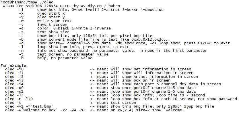
The oled program has 14 functional parameters:
“-i” Followed by 0~3, show some common status of the box
“-x/-y” With the xy coordinates of the displayed content
“-w” Followed by the displayed text content
“-v” Followed by 0/1,0 is reverse display, 1 is normal display, and the default is normal display
“-c” Followed by 0/1/2, the displayed color, 0 is black (off), 1 is white, and 2 is reverse display
“-s” Font size
“-f” This parameter is very useful, to display the bmp file, the bmp file must be: monochrome, 128×64 pixels
“-b” Display mode conversion files, mode files can be make by PCtoLCD2002 software
“-d” Display the value of the first 5 channels of each output port, followed by 0 or 1, -d0 means only display once, -d1 will display in a loop until you press CTRL+C to exit
“-l” Any information of the box is displayed alternately, -l is followed by the displayed time in seconds, press CTRL+C to exit
“-n” The box password will not be displayed, and the password will be replaced by “*”, This parameter must be placed in the first parameter to be valid, no parameter value
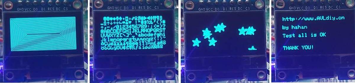
“-t” Automatic test screen, no parameter value
“-h” Help, no parameter value
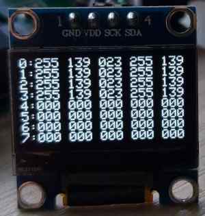
“oled -d1” will loop display the value of the first 5 channels of each output port, can checking the output status
Q14: How to use GPIO?
![]() There is a set of standard GPIO operation methods under linux system, but it is very cumbersome. You need to export the IO port first, then set the direction of the IO port, and then read and write, which is not a general annoyance. In response to this problem, we have developed a set of GPIO special programs, which are simple and easy to use. The specific usage methods are as follows:
There is a set of standard GPIO operation methods under linux system, but it is very cumbersome. You need to export the IO port first, then set the direction of the IO port, and then read and write, which is not a general annoyance. In response to this problem, we have developed a set of GPIO special programs, which are simple and easy to use. The specific usage methods are as follows:
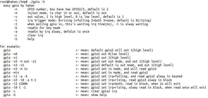
The gpio program has 9 functional parameters, but don’t be afraid, many parameters can be defaulted, just need to understand a few commonly used parameters:
“-n” Followed by the pin number of GPIO, the box has 3 groups of GPIO, almost 70 IO ports, but many IO ports are multiplexed and cannot be used at the same time, only GPIO2 and GPIO3 are reserved as general IO ports;
“-m” Input and output mode, switch the direction of the IO port, followed by the characters “in” or “out”;
“-v” The output value of the IO port, followed by 0 or 1,0 means output low level, 1 means output high level;
“-i” IO port input interrupt mode, there are rising edge trigger, falling edge trigger, both trigger 🛫, followed by 0~3, 0 is rising, 1 is falling, 2 is both, 3 is none, If this understanding is a bit difficult, you can ignore it for the time being;
“-t” A polling waiting time when reading the input of the IO port, in ms, if it is -1, it will be blocked until the value of the IO port is read.
“-k” Button mode, no parameter value, if the IO port is connected to the button, the program will de-jitter processing, and the button will print “down” when the button is pressed. You can determine whether the button is pressed by judging the “down” character;
“-a” No parameter value, it will always read the IO port in a loop, if you do not add -a, it will only read the IO port once;
“-c” No parameter value, clear the interrupt set last time, single command;
“-h” Show help, no parameter value
Most of these parameters are for input, and output is relatively simple, only -v and high and low levels are required. Assuming that GPIO2 is connected to a relay, the relay is high-level on, and the low level is off. The relay is connected to the power supply of the electric curtain. The curtain can be pulled up in about 15s. We can write a script to trigger:
gpio n2 -v1 #open relay power
sleep 16 #delay is 16 seconds. It doesn’t matter if you delay a few more seconds. The curtains generally have a limit switch, and they will limit when they are opened.
gpio n2 v0 #relay power off
light 0 s 1 255 #open all lighting
lightplay /mnt/mmcblk0p1/open.wav #play prompt sound
The simplest test method for gpio: You can connect the positive pin of a led light to gpio and the short pin to gnd, and input gpio -v1, the led light will be on; input gpio -v0, the led light will be off.
Q15: How to use built-in effects?
 The box comes with a built-in effect generator program effects , The effects function is very powerful, There are as many as 19 parameters and 54 basic effects, 54 basic effects can be output without any external equipment and software, These built-in effects can be changed by changing the values of 18 parameters, and thousands of effects can be combined. There are a lot of parameters, but don’t be afraid. You can apply these parameters flexibly after understanding. The 19 parameters of effects are in no order and you can write them casually. You can add spaces or no spaces between the parameters and the parameter value.
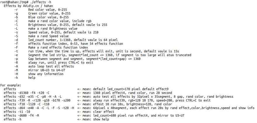
effects takes 2 types of parameters, among which the lowercase parameters need to have parameter values, for example -r255 -g0 -b0 means the color is red, and the three primary color values;
Parameters with uppercase letter have no parameter values, for example -C means random color values will be generated. The specific instructions are as follows:
“-r” Red color value, 0~255;
“-g” Green color value, 0~255;
“-b” Blue color value, 0~255;
“-C” Randomly generate values of different colors, without parameter values;
“-l” The value of main brightness, 0~255;
“-L” Randomly generates different brightness values, without parameter values;
“-s” The speed value of effect running, 0~255, if not filled, the default value is 210;
“-S” Randomly generate values of different speeds, without parameter values;
“-d” The number of LED light pixels, can be filled in from 1 to 1360 pixels. If it is not filled in, the default value is 64 pixels, which can be understood as the pixels of a single lamp, 1360 means all lights as a matrix;
“-f” The effect function index number, 0~53, the effect of 0 is static color, the other numbers are changing effect, totally 54 kinds of effects;
“-F” Randomly generates different effect function index numbers, without parameter values;
“-t” The time to run the effect, in seconds. If the time is up, the effect will be exited. If it is left blank, the default is 15 seconds;
“-e” The light strip is divided into segment, which can be understood as the number of connections for a single lamp or understood as the fixture patch number, this needs to be used in conjunction with -d;
“-p” The space between the segments of the light strip. The lights of this space will not be displayed. This needs to be used in conjunction with -e, -d;
“-R” The effects will always run, will not exit, there is no parameter value, no matter the time of -t, you need to press CTRL+C to exit, or press the Q key on the remote control (corresponding to the key value KEY_Q);
“-A” Automatically loops to test each effect from function index 1, there is no parameter value, and can be combined with other parameters to change the color, speed, time, etc.
“-M” Mirroring function, will mirror the effect of U0~U3 to U4~U7, that is mirror the effect output from the SPI-LED first line to the second line;
“-H” Will display some debugging information, without parameter values;
“-h” Displays help information, no parameter value
For example:
1: If I have 10 sets of 12 pixels (36 channels) RGB lights combined into a circle, as shown in the figure below, if I want this circle to automatically run 1 to 54 effects, the color and brightness of each effect are different and change randomly What should I do if each effect runs for 20 seconds? If there are more than N such circles, what should I do?

In the first case, you only need to enter this command: effects -d12 -e10 -A -C -L -t20 can meet this demand; In the second case, you only need to change -e10 to the total number of fixture that need to be combined into these circles N*10. For example, if there are 10 circles, 100 fixture are needed, so change it to: -e100. Or this example, if I want to make 3 pixels (9 channels) between the circle and the circle not to be displayed, what should I do? Just add the -p3 parameter.
So the proposition becomes this: 100 sets of 12-pixel RGB lights, each 10 sets to form a circle, a total of 10 circles, there are 3 pixels not show between the circle and the circle, what should be done?
The command becomes this: effects -d12 -e100 -p3 -A -C -L -t20 , After entering the command, you can pick up the coffee and enjoy the super cool effect slowly. I promise not to disappoint you.
2: If I only want to use effect No.10, what should I do? enter: effects -f10 -d12 -e100 -p3 In this way, the 10th effect will run for 15 seconds by default, or you can add the -t parameter to define the running time. What if you want to keep running? Just add the -R parameter and the command becomes like this: effects -f10 -d12 -e100 -p3 -R
3: If I want to treat the 8 universe as a whole, such as a matrix, what should I do? Just enter the command effects -d1360 -A -F -H , parameter -d1360 means all pixels, -A means that 54 effects are automatically run, -F means that the effect will be randomly selected, -H means that some information will be printed for us to see.
Special attention is needed:
1: Effect generator program effects it can only generate the effect of 3-channel RGB lights or matrix lights. The lights can be connected to DMX512 lights or WS281x lights, but cannot generate the effect for computer lights, because the channels of computer lights from different manufacturers are different and irregular. So there is no way to be universal. effects it can be considered as a simple command-line version of Madrix program. The version will be upgraded in the future. The function will be more powerful and more effects will be added. I plan to add more than 200 effects. Please pay attention to the upgrade information on our website.
2: effects defines 15 key functions. If the box is connected to a USB keyboard or the infrared remote control is set according to the above Q10 method, then the effects can be controlled in real time through the keyboard and remote control.
The “V” and “<-” left direction keys are defined as the previous effect function;
The “N” and “->” right direction keys are used as the next effect function;
The “up direction” key used as a brightness increase function;
The “down direction” key is used as the brightness reduction function;
The “P” key and “Space” key are used as the color change function, each time you press it, the color will change randomly;
The “Q” key as the exit function;
The “R” key as red function;
The “G” key as a green function;
The “B” key as blue function;
The “W” key as white function;
The “F1” key is used as a speed increase function;
The “F2” key serves as a speed reduction function.
You can change the effect being generated in real time by pressing these keys.
3: Many effects require a certain contrast between the background color and the changing color to make the effect obvious. If the background color is the same as the changing color, you will not see the effect change. Please change one of the color values to see the effect change.
4: The simple use of the built-in effects can also be operated through the [Lighting Test] of the webui, which can be operated by pressing the mouse. if “ColorRealOut” is checked, the color will be output to the light in real time when the color is changed. The “AutoPlayAll” button will play all the effects in the background, corresponding to the command line “-A” parameter. At this time, if you change the color, brightness, and speed, the lighting effect will change in real time, but other parameters can’t change in real time, it will change in the next effect. If you are playing the effect, it is better not to check “ColorRealOut”, otherwise if you change the color of the color wheel, the colors will overlap. If the value of the “Run Time” fader cannot be changed accurately with the mouse, you can change it by pressing the left and right keys on the keyboard.
Q16: How to use SD card and USB disk?
![]() The sd card, usb disk and many devices must be mount then can be used when push to the linux system. The mounting method is more troublesome, not suitable for newcomers. But don’t be afraid, our box has an automatic mounting script, Inserting the SD or USB disk into the box will automatically mount it and you can use it directly. The sd card will be automatically mounted to the directory “/mnt/mmcblk0p1”, the USB disk will be mounted to “/mnt/sda1”, If there are multiple USB disks, they will be mounted to “/mnt/sda2…n” in turn. These directories are equivalent to the D drive, E drive, F drive of windows…
The sd card, usb disk and many devices must be mount then can be used when push to the linux system. The mounting method is more troublesome, not suitable for newcomers. But don’t be afraid, our box has an automatic mounting script, Inserting the SD or USB disk into the box will automatically mount it and you can use it directly. The sd card will be automatically mounted to the directory “/mnt/mmcblk0p1”, the USB disk will be mounted to “/mnt/sda1”, If there are multiple USB disks, they will be mounted to “/mnt/sda2…n” in turn. These directories are equivalent to the D drive, E drive, F drive of windows…
Special attention is needed: The second network port LAN1 cannot be used when using an SD card, because these two devices are multiplexed. Switch the multiplexing mode in webui [BOX SETUP]->[SD/PWM/UART2 or LAN1], or use the command line: setbox -C SD to switch to SD card mode, setbox -C LAN1 to switch to the second network port LAN1 mode . The second network port LAN1 is still quite annoying. The pins are also multiplexed with pwm and uart2. After switching to LAN1, pwm and uart2 cannot be used either.
Q17: How to use USB?
![]() The USB interface of the box can connect to the USB disk, also can connected to USB sound card, USB keyboard, USB mouse, USB-RS232, USB-Hub expansion USB interface, etc… most general USB devices do not require drivers, some devices need to install drivers before they can be used, devices like USB-RS232 need special drivers.
The USB interface of the box can connect to the USB disk, also can connected to USB sound card, USB keyboard, USB mouse, USB-RS232, USB-Hub expansion USB interface, etc… most general USB devices do not require drivers, some devices need to install drivers before they can be used, devices like USB-RS232 need special drivers.
Please Note: If you want the box to play music, you must insert a USB sound card into the box, and the sound comes from the sound card.
Q18: How to cascade multiple devices?
![]() The box has two 10M/100M self-applicable network ports LAN0 and LAN1. These two network ports are set to pass through, so you can connect N multiple boxes hand in hand through a network cable for cascading, no switch or router is needed, The box itself has switching and routing functions. The IP of the box’s LAN port is set to a static fixed IP, The factory default IP address is 192.168.7.1, so the cascaded box needs to be changed to a different IP to avoid conflict, The IP of the cascade box can be changed to: 192.168.7.xxx, as long as the xxx is different.
The box has two 10M/100M self-applicable network ports LAN0 and LAN1. These two network ports are set to pass through, so you can connect N multiple boxes hand in hand through a network cable for cascading, no switch or router is needed, The box itself has switching and routing functions. The IP of the box’s LAN port is set to a static fixed IP, The factory default IP address is 192.168.7.1, so the cascaded box needs to be changed to a different IP to avoid conflict, The IP of the cascade box can be changed to: 192.168.7.xxx, as long as the xxx is different.
Please Note: Because the LAN1 port is multiplexed with SD/PWM/UART2, if you want to cascade the LAN, you must switch the box to the network port LAN1 mode, otherwise the network port LAN1 cannot be used, and LAN0 does not have any functions multiplexed, It is a good habit to use LAN0.
Q19: How to upgrade?
![]() The box upgrade is very simple, Enter the default IP of the box: 192.168.7.1 through the address bar of your mobile phone, tablet or computer browser, you can open our box’s webui, browse our firmware in the [BOX SETUP] of webui, and press “Upgrade” to confirm after that, the box will automatically complete the upgrade. Another method is: if the box is connected to the Internet, you can run our upgrade software, and the box will automatically download the firmware from our server, after our server detects that the box SN is correct, it will automatically complete the upgrade. This method requires downloading the firmware online, because The firmware is relatively large and our download server network speed is uncertain, causing the download uncertainty, so it is not recommended.
The box upgrade is very simple, Enter the default IP of the box: 192.168.7.1 through the address bar of your mobile phone, tablet or computer browser, you can open our box’s webui, browse our firmware in the [BOX SETUP] of webui, and press “Upgrade” to confirm after that, the box will automatically complete the upgrade. Another method is: if the box is connected to the Internet, you can run our upgrade software, and the box will automatically download the firmware from our server, after our server detects that the box SN is correct, it will automatically complete the upgrade. This method requires downloading the firmware online, because The firmware is relatively large and our download server network speed is uncertain, causing the download uncertainty, so it is not recommended.
Please Note: The upgrade has a certain risk, do not touch or turn off the box power during the upgrade, otherwise it may cause the box to become like a brick, can’t be used never, that are not covered by the warranty. so please pay special attention.
The upgrade time takes about 3 minutes. You can see the 5 LED lights to check if the upgrade is complete, during the upgrade, the red light will flashing and the yellow light will stop flashing, If one of the two yellow lights flashes again, it means the upgrade is successful and the box is normal started.
There is one more point to note: For some electronic enthusiasts, please do not burn other firmware to our box flash by yourself, burning the box falsh will also be regarded as an automatic waiver of warranty rights. inside our box have two cpu in one-to-one correspondence, If one of the flash firmware is destroyed, it will no longer correspond, and the box’s functions will be lost or unstable from time to time.
Q20: What is the state of the box when it leaves the factory?
![]() The factory default state of the box is as follows:
The factory default state of the box is as follows:
1: Default Wifi is turned on; Wifi SSID: hahan_light; password is: AVLdiy123 (recommended to change the password or turn off wifi)
2: Default IP: 192.168.7.1; Mask: 255.255.255.0; Wifi is DHCP; LAN0, LAN1 are static fixed IP.
3: Factory default: LAN0, GPIO, UART0/1, USB can be used, SD/PWM/UART2 can be used, LAN1 cannot be used, if you need to use LAN1, please switch in webui.
4: Default output: DMX512 output mode; if you need LED SPI output, please switch in webui.
5: Artnet default: net is all 0; subnet is all 0; univese are: 0, 1, 2, 3, 4, 5, 6, 7 .
6: Default login username: root; password: AVLdiy123 (recommend to change this password)
Q21: How to connect different lighting equipment?
![]() The box can control DMX512 lamps or DMX512 devices, and can also directly control ws281x LED strips. However, DMX512 and LED SPI output cannot be used at the same time, They need to be used by switching the output mode. The switching method can be switched in the [BOX SETUP] of webui, and it will be automatically remembered only after switching once.
The box can control DMX512 lamps or DMX512 devices, and can also directly control ws281x LED strips. However, DMX512 and LED SPI output cannot be used at the same time, They need to be used by switching the output mode. The switching method can be switched in the [BOX SETUP] of webui, and it will be automatically remembered only after switching once.
1: The box has 8 DMX512 output ports, each port is a standard 512 channel output, so the total number of channels that can be controlled is: 8×512=4096 channels. The international standard wiring method of DMX512 is: 3+ 2- 1GND, the box is according to the international standard, and it is also 3+ 2- 1GND. For details, please refer to Figure 3 above.
The software and hardware of the 8 output ports of the box are separate, and they do not interfere with each other, It is different from the early Artnet, Each port has an exclusive 16bit address, The ID number can be changed to any value from 0 to 65535, It is very free . can be understood as 8 artnet devices with independent 1-port output are combined into a box, and each port is an independent Artnet device.
Please note: Many people think that GND all is connected. In fact, for isolation, the signal, power, and GND of different DMX512 output ports are completely independent and different. Therefore, don’t take the GND of different DMX512 port together, This is a wrong connection, If the GND is connected together, it may cause the phenomenon that cannot be isolated or controlled. Each port is independent and has a big advantage, Even if the power is connected by mistake, it can only burn the connected port, which will not affect the other port, The other port can continue to be used to play a surplus.
2: The box can also directly control WS281x\APA\SK… and other LED strips that also serve as the timing of WS281x, The timing of WS281x is 800K single-line control. Because the LED particles are relatively dense, 512 channels can control 170 3-channel RGB pixels, The number of lights is a bit less, so the SPI LED output of the box out 4 universe on each line, and each line is connected to 680 3-channel RGB pixels, Only 2 wires can out 8 universe, corresponding to U0~U7 of DMX512 , A total of 1,360 3-channel RGB lights can be controlled.
The wiring of the LED-SPI port is: pin 1 is the ground wire, the ground wire of the LED strip needs to be connected with the ground wire of the box; pin 2 is the output of port 0~3, and the corresponding DMX512 universe are U0, U1, U2, U3, these 4 universe will be spliced inside the box; pin 3 is the output of port 4-7, corresponding to DMX512 universe are U4, U5, U6, U7.
Please note: The first pin of the box is the ground wire, which needs to be connected with the ground wire of the LED strip and the power supply ground wire for the LED strip; the 2 and 3 pins of the box are respectively connected to the DI of the LED strip, Note that it is not DO, Someone connects to DO by mistake. There is also a box that outputs a control signal, not a power supply, so the LED strip needs its own external power supply, and the ground wire of the power supply also needs to be connected with the ground wire of the box. The LED strip, the power supply, and the box LED-SPI output GND need to be connected together, if not connect, the LED strip will flicker.
Q22: How to check box good or bad?
When you enter http://192.168.7.1 through the browser, click [MANUAL], if you can see this page now, you can basically conclude that 90% of the box is good, and then click [LIGHTING TEST] above to open the web console and push Inside the fader, or click on the “AllTo0” and “AllTo255” button to see if the connected lighting has changed. If the lighting does not change, you can basically determine the wiring problem, Please check whether the wiring is correct. The correct wiring of DMX512 is: 3+ 2- 1 to ground.
attention please:
Because the DMX512 protocol is a complete data chain, the data chain of each packet must be complete to form DMX512. Therefore, DMX512 control will not have a phenomenon that one lighting fixture or one channel can be controlled, but other lighting or other channels cannot be controlled.
It will only appear: either it can be controlled or neither can be controlled. If there is a lighting that cannot be controlled in the middle, please check whether the line or lighting is good or bad, or check whether the address code corresponds. The LED-SPI control is also the same.
Q23: How to make secondary development?
![]() There are at least 5 ways of secondary development of the box:
There are at least 5 ways of secondary development of the box:
1: According to our network protocol format, develop by writing PC program by yourself;
2: Connect USB-232 to our box through the USB interface, and conduct secondary development through RS232 serial communication, the protocol can be defined by yourself;
3: Through external module and mcu connected to our box’s UART or I2C for secondary development, the protocol can be defined by yourself;
4: Develop directly inside the box, no additional things are needed. The box itself is a computer, but the system of the box is linux, not the commonly used windows. The linux shell is powerful, and the box can be easily developed through shell scripts, similar to the case above.
5: The box is also a server, which can be remotely controlled via web or ssh to achieve development purposes. Similar to our webui, you can write a web page to control it yourself.
Please note:
What needs to be reminded is: The box has the ability and platform for such secondary development, but it must be completed by the customer with such knowledge and technical reserves. These functions can’t be implemented directly when get the box, need the user to write code according to their own project requirements to achieve it. If the user does not have such technical strength, you can pay to find an agency company to write. Note: Secondary development as a technical output requires paid support, not free technical support.
Q24: How to install and remove software?
![]() Installation method: First download the required software from our website, The software is in ipk format. For example, if you need to install the CH341 USB-RS232 serial cable driver, you need to download CH341 driver ipk software packages, it is kmod -usb-serial-ch341.ipk, and enter the command: opkg install kmod-usb-serial-ch341.ipk then will install the driver of CH341, now insert CH341 USB-RS232 serial cable to the box, the device file “/dev/ttyUSB0” will appear in the box, and you can operate this serial port through our command line serial debugging assistant [uart].
Installation method: First download the required software from our website, The software is in ipk format. For example, if you need to install the CH341 USB-RS232 serial cable driver, you need to download CH341 driver ipk software packages, it is kmod -usb-serial-ch341.ipk, and enter the command: opkg install kmod-usb-serial-ch341.ipk then will install the driver of CH341, now insert CH341 USB-RS232 serial cable to the box, the device file “/dev/ttyUSB0” will appear in the box, and you can operate this serial port through our command line serial debugging assistant [uart].
![]() Remove method: Enter the command: opkg remove kmod-usb-serial-ch341 then can remove the ch341 driver. It should be noted that if the box is restored to factory settings, all the programs installed by opkg will be remove.
Remove method: Enter the command: opkg remove kmod-usb-serial-ch341 then can remove the ch341 driver. It should be noted that if the box is restored to factory settings, all the programs installed by opkg will be remove.
Q25: Why can’t browse the box when I enter 192.168.7.1 in the browser?
![]() Please note that the browser input is http://192.168.7.1 , not https://192.168.7.1 , If you add an s, you cannot browse the box. Many browsers will automatically add an s .
Please note that the browser input is http://192.168.7.1 , not https://192.168.7.1 , If you add an s, you cannot browse the box. Many browsers will automatically add an s .
Q26: how to Warranty
![]() The box is guaranteed according to China’s three guarantees policy, But only for normal use, If the following conditions occur, it will be deemed to automatically waive the warranty rights:
The box is guaranteed according to China’s three guarantees policy, But only for normal use, If the following conditions occur, it will be deemed to automatically waive the warranty rights:
1: Tearing the box seal
2: If you don’t have certain electronic knowledge, GPIO DIP is connected randomly and the chip is burned;
3: Root login accidentally deletes system files;
4: Change box bootload, or change the box flash firmware;
5: Misoperation burning chip (such as water into the box, wrong connection of strong current, etc.);
6: The flash is damaged due to power failure during the upgrade;
7: The box SN check is incorrect;
All of the above will be regarded as the behavior of the customer waiving the warranty rights automatically.
Also: the use of any software and secondary development is not covered by the warranty.
The two main CPU chips in the box are equipped with protective circuits. Normal use will not cause burn out. The main chip will be burned only the voltage is higher than the chip’s withstand voltage or a direct short circuit by mistake.
Q27: how to buy?
You can go to our Taobao link to buy: https://detail.tmall.com/item.htm?id=630984870508, If foreign customers do not have Taobao ID, they can buy through our agents here: http://www.aliexpress.com
Thank you for your support.